CE-152 : The Sharp tape player/recorder for the PC-1500

A robust pocket computer must have a robust tape player/recorder !
And the CE-152 is this tool.
It’s a well known PC-1500 + CE-150 extension, the best to save/load programs.
EMI_2614

It’s a flat player in a brown protection. On the side you have the record/play connectors, a remote entry, the volume and tone potentiometers.
EMI_2427 EMI_2428
EMI_2429 EMI_2430

And in the box, the user manual, an earphone and 3… don’t know the word in english but in french it’s “coton tige”. The tape is not included but nice to see on this picture.
EMI_2619

CE-152_User_manual_MultiCE-152_User_manual_Japan
DownloadDownload

BMC : The MC-12 (Part III)

To read more a out the MC-12(A) there was an article in the german magazine CHIP :BMC_MC-12-PC-1500_ZeitungDownload article

Here if the translation (may have errors)

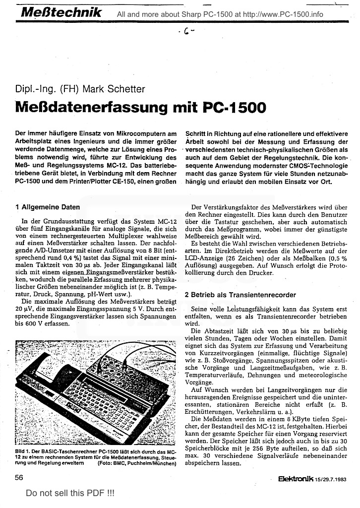
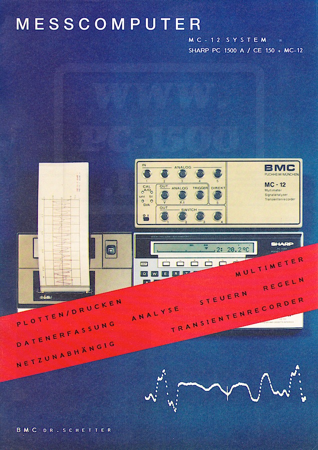
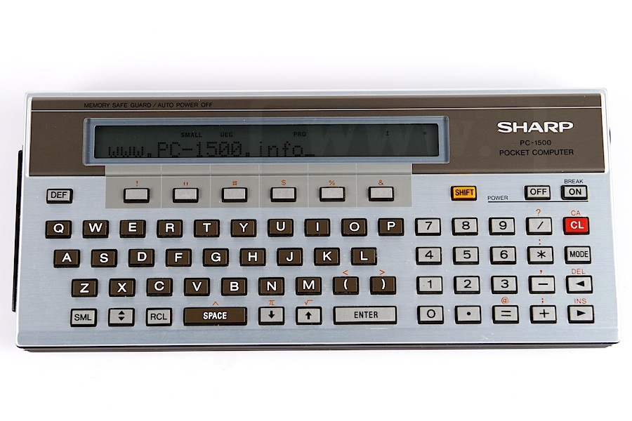
Data acquisition with PC-1500

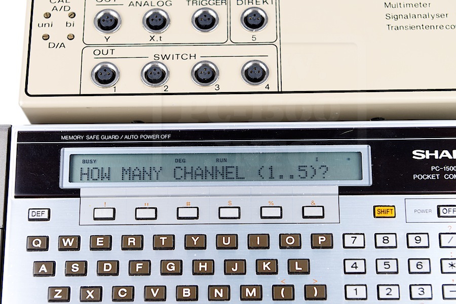
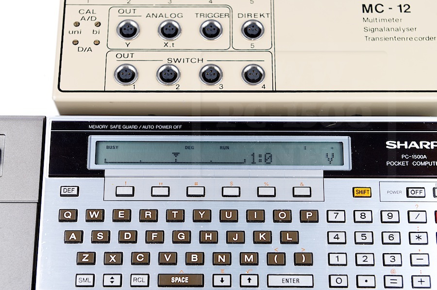
The More frequent use of microcomputers in the workplace of an engineer and the ever increasing amount of data that is necessary to solve a problem, led to the development of measurement and control system MC-12th The battery-operated device, when paired with the computer PC-1500 • and the Printer / Plotter CE-150, a major step towards a more rational and effective work in both the measurement and recording of various technical and physical sizes, as well as on the field of control engineering. The consistent application of modern CMOS: Technology makes the whole system for many hours mains-dependent and allows the use of mobile on site.

1 General data
The basic version of the System MC-12 has five input channels for analog signals, which can be switched by a computer-controlled multiplexer selectively on a measuring amplifier. The subsequent A / D converter with a resolution of 8 bits (corresponding to approximately 0.4%) samples the signal with a minimum cycle time of 30μs. Each input channel can sieve with a private Eingangsmeßverstärker bestükken, whereby the parallel detection of multiple physical sizes next to each other is possible (eg. 8. temperature. Pressure, tension, pH, etc.).
The maximum resolution of the instrumentation amplifier is 20 microvolts, the maximum input voltage 5V. By appropriate input amplifier is voltage up to 600V can be recorded.

The gain of the sense amplifier is set by the computer. This can be done by the user via the keyboard. but also automatically by the test program, with always the cheapest range is selected.
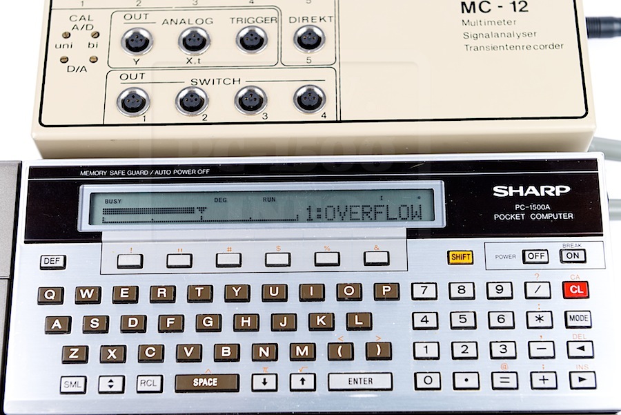
There is a choice between different modes. In direct mode, the measured values ​​on the LCD display (26 characters) or as a measuring beam (0.5% resolution) will be issued. Upon request, the logging is performed by the printer.

2 Operating as a transient
Its full potential can only develop the system when it is operated as a transient.
The sampling time can be set from 30 microseconds up to any number of hours, days, or weeks. This sieve is the system for the collection and processing of short-term operations (single, fleeting signals) such. As shock processes, spikes or acoustic events and Langzeitmeßaufgaben such. As temperature gradients, strains and meteorological processes.

Only the outstanding events are stored on request for long-term operations and uninteresting, stationary regions not covered (eg. As shocks. Traffic noise, etc.).
The measured data are in an 8K deep memory, which is part of the MC · 12 detained. In this case, the total memory can be reserved for a task. However, the memory can also be found in up to 30 memory blocks divided by 256 bytes each, so that max. Allow 30 different waveforms next to each store.

To select particularly interested in the parts of the signal, the ratio of pre / post-history in eight levels can be selected. The Aussteuerunganzeige the measured values ​​by means of LCD bar.
The stored values ​​can be either applied directly to two analog outputs or arithmetical previously subjected to signal processing and analysis.
A measuring process was taken and stored by MC-12, the signal can be tapped at one of the analog outputs. The output voltage is ± 5 V to 100 ohms. A single signal or an arbitrarily long lasting measuring controls so that the Y • Input a recorder. The output speed is selectable and is suitably adapted to the setting speed of the recorder. The time axis is directly from the recorder or the computer – second analog output of the MC-12 to X input of the recorder – controlled.

Two different signals y1, y2 (eg pressure with temperature) was added, may either both signals as a function of time (y1 (t), y2 (t)) are plotted, or a signal is shown as a function of the other (y1 = y1 (y2)); Here are the outputs of the MC-12 are located on the xy-inputs of the external plotter.

(Adjustable repetition time) by a constant repetition of the signal sequence is a signal to the oscilloscope can be mapped to each of the analog outputs. An additional trigger output ensures a stable display. By this way any normal oscilloscope is digital oscilloscope for Spiecher, coupled with the other advantages of the MC-12th

The integrated printer / plotter documents the results of measurements and plots with a resolution of 0.2 mm with the available four ink colors are especially useful for playing various signals in conjunction with ten line types. The scaling of the appropriate coordinate systems is done automatically by the computer.

3 Application Examples
To give an idea of ​​the possibilities offered by the system described here, are below a grater typical applications together provided for which computing functions of the PC-1500 come to fruition. The collection can of course do not claim to be complete.

3.1 detection of oscillation process
The ringing of an electric
Resonant circuit is detected by the MC-12 (Figure “J).

The yt · Scaling was performed by the computer. The calculated values ​​from the computer and k f follow directly the time function of the damped oscillation
y (t) = A * exp (-ky) * sin (2PIft)
and the differential equation when a component size is known.
L · R · y + y + y / c = 0

3.2 Frequency Analysis
A periodic progress will be measured, stored and plotted by the MC-12. Subsequently, the frequency components of the process are calculated and printed and displayed as a bar graph (Figure 4).

3.3 reverberation time
In a space to be examined E is generated in a stationary sound field using a loudspeaker. After switching off the sound source, the time course of the decrease in sound level is measured on a logarithmic scale, stored and plotted according to the physical definitions by determining a regression line, the reverberation time T is determined (Figure 5).

3.4 Programmed signal analysis and processing
The essential advantage of the combination MC-12 / PC-1500 compared to other systems, the signal processing. From the simple logarithm to the Fourier analysis extends the range of possibilities. The user has the choice, in addition to the predefined processing variants using BASIC programs to transform the measurements according to his needs and evaluate. For complicated special solutions are custom software.

3.5 Digital control and regulation
Additional applications which are beyond the scope of traditional instruments, the system MC-12 offers in the field of control engineering. With four CMOS switching outputs (75 Ohms, 50 mA, +/- 10V), two relays and two analog voltage outputs (+/- 5 V) provides many possible keys.
From a simple timer display over two-point control to complicated PID control system is the system load no application is closed. Simple programs for control and regulation are included in the system of the MC-12.
With the help of detailed documentation, the user can create self-measurement and control applications. For this, 11 Kbytes program memory in the PC-1500 free for the user.

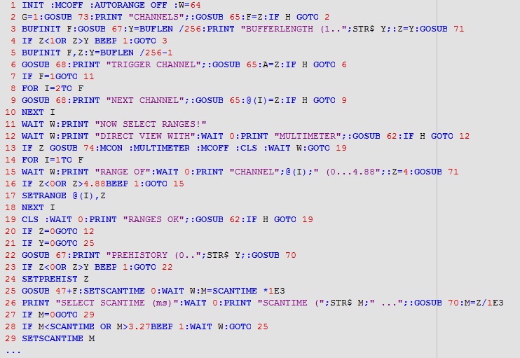
4 Dialog oriented user guidance
The Measurement and Control System MC-12 was designed so that the user does not have to deal with the function of additional controls. All functions of the MC-12 can be controlled via the alphanumeric keypad in dialogue with the computer. Operator errors are reduced to a minimum. Incorrect entries complained about the program itself. Once made settings can be saved and recalled when needed. This reliable reproducibility of test results is ensured. An additional check of the measurement parameters are documented on the printer.

Generous donor : Oscar Rysdyk from Holland

At the beginning of December Oscar Rysdyk, from Holland, contacted me after finding my site by Google.
He wanted to offer me his own first hand PC-1500.
This one was purchased in the united states by his father.

Lets examine this PC-1500…
Do you see the serial number on the last picture ?
It don’t have any metallic grey paint.
This is same for all USA models, i think.

Thank you very much Oscar for this gift !

Oscar, you’re a photographer ! These pictures are very nice.
Unknown
Unknown-1
Unknown-2

BMC : The MC-12 (Part II)

Inside the MC-12 it’s a professional assembly. As in the MC-12, all ICs are on sockets.
BMC_MC-12_010
No battery here, the system needs a power adapter.
The build is same, a main board and piggy-pack modules. We can see some double connectors on the right for, maybe, some filter ?
BMC_MC-12_011
Under the AD/DA board we have :
– 2 RVS Roms with the firmware
– 4 static memory ICs with a total of 8Kb !!
BMC_MC-12_013

There is a Basic program stored in the Rom. It’s the named “MC 12.QAS”
BMC_MC-12_QASDownload the user manual

The program is a good example for the new Basic instructions :
QASDownload the program

And here is it running :
BMC_MC-12_014

BMC_MC-12_015 BMC_MC-12_016

Next time we will the optional modules and some industrial use.

Frank C. Odds : Probe! a disassembler for the Sharp PC-1500

Another gift from Frank C. Odds : Probe!

PROBE_001
Frank tells us :

PROBE!
Writing PROBE! (ca. 1984) was the only time I ever made money from working with the PC-1500. The biggest problem with Sharp’s wonderful pocket computer was that it had no compiler. You wrote programs in BASIC, and when they ran, the computer painfully interpreted each step from BASIC, line by line, and thus executed the instructions.
In any computer processor, the ‘true’ inputs and outputs are bytes of binary symbols, e.g. 10011000 011011110 etc. No human brain can seriously contemplate writing complex programs this way, but if each 8 binary digits (each byte) is written as a hexadecimal number (the previous example would be 98 DE) they become slightly easier to deal with. A program written as a series of hexadecimal bytes poked into successive memory locations is described as ‘machine code’.
Machine code still requires a pretty giant intellect to put together hexadecimal bytes in a way that constructs a useable program. It would be handy to have a programming language less complex than BASIC, but which makes better sense than a string of bytes. Such a language is known as ‘assembler’. Its details depend on the precise way the computer’s central processing unit (CPU) functions.
The PC-1500 CPU works with three ‘registers’, X, Y and U, each of which can hold 2 bytes, an accumulator (A) and a small number of other components with names such as ‘program counter’, ‘timer’, and ‘carry flag’, but I’m trying to keep things here as simple as possible! Programming then becomes a sequence of loading numbers into various registers, getting the accumulator to work on them, and many remarkably small steps which, between them, perform the functions you want.
The bottom line: a high-level language like BASIC is fairly easy to understand as a series of English-language instructions. Assembly language — a lower-level language — looks like gobbledygook, but it is a labguage one can learn, and it gets much closer to the way the CPU truly functions.

PC-1500_Technical_Reference_Manual_001

In the early 1980s, Sharp published their Technical Reference Manual for the PC-1500. This gave a lot of information on the PC-1500’s hardware and software. Critically, it explained and detailed the instructions that could be handled by the CPU in both assembly code and its machine language equivalents. This made it possible for users to write complex programs in assembler, and to poke the corresponding machine code into the PC-1500 memory. The result was a program that ran many, many times faster than a BASIC program.
I loved the whole challenge of writing complicated programs in assembler and was (then) young enough to learn the language and remember the many commands. I must have spent many hours with the Technical Reference Manual at my side: many of the pages are now completely loose!
The Sharp Technical Reference Manual was a really nicely produced book. As well as very thorough descriptions of PC-1500 assembler language, it also showed how the PC-1500 memory (ROM and RAM) were laid out. What it did not provide was details of the Sharp proprietary machine code that interpreted user’s BASIC programs. Consider a line such as this…
10: INPUT “What is your name? ”; A$
You know that, somewhere in the computer’s memory, there is a machine-code routine that displays the string “What is your name? ” and waits for you to input A$, which is then passed somewhere to memory. But you have no idea of the memory address where that machine code starts to run.

Probe_Fig_1Fig. 1

So I wrote PROBE! It’s a kind of reverse assembler. When you run PROBE! you input a memory address and the program prints out the machine code that starts at that address. In fact, it does a lot more, because PROBE! doesn’t merely read the hex bytes: it reverse-interprets the machine code so a sequence of assembler instructions is printed out by the CE-150. The user can even select an option for PROBE! to follow branches and jumps in assembler, in which case the output should reflect precisely the way a particular routine carries out its function. The catch is that you have to be lucky or accurate in your chosen starting memory address, or the output will not be helpful. It’s the equivalent of translating DNA codons out of phase.
When I’d finished putting PROBE! together, I contacted Ronald Cohen, who produced the monthly magazine called Status 1500. PROBE! was far too long and complex a program for Ronald to print it in the magazine, and for readers painfully to copy it to their PC-1500s. The answer was to sell the program ready loaded on cassettes. (It may seem incredible, but the idea of paying for ready-to-run software was still pretty novel in the mid-1980s!)
Ronald advised I should charge a high price. I was unhappy to do so: I was unsure how well the tape cassettes I produced would run on other people’s set-ups, and I have never really been an entrepreneur. I advertised the program in Status 1500 at £4 per cassette. To my amazement, I received about 30 orders, all within just a couple of weeks.
Let me end this story with a confession. I hope the people who bought PROBE! had more success with it than I did myself. I quickly tired of randomly guessing where built-in routines might start, and ultimately I just developed the skill to write my own assembler code. As far as I can recall, I never used any output from PROBE! to help me develop my machine-code programs!

You can download Probe! files here :
User manual, Bas file, Wav file

Thank you very much Frank !!!
Readers, enjoy this gift and thank you for your feedbacks.

Fig. 1. The opening of my machine code program EASI-THOUGHT from the hand-written original. In the left-hand column I have noted what a routine does. The centre column shows the instructions in assembler, and the right-hand column gives the appropriate machine code hexadecimals, as copied from the Sharp Technical Reference Manual.

Sharp PC-1500 serial 100xxxxY one of the first ?

Just after Christmas my friend CGH was at home for a “PC-1500 day”.
We have talked, tinkered and exchanged some machines.
I’m proud to present you this one : the oldest PC-1500 i know !
(Except his one with a lower serial number)

Externally there is no change, it’s a PC-1500.
PC-1500-A01-1001_003 PC-1500-A01-1001_002

And on the back the only difference is the serial number :
PC-1500-A01-1001_001

But let’s opening the machine :
It’s strapped like a A01 ROM. Uh… these straps are white ! The first time i see one like this.
PC-1500-A01-1001_004

We can see on the SC613128 IC that it’s a A01 ROM.
The biggest white strap is mine, to repair a memory access problem.
Do you see the diodes on straps ? First time too…
PC-1500-A01-1001_006
PC-1500-A01-1001_005

Ok, more ?
The display board version is F2025, the oldest i know.
PC-1500-A01-1001_008

And the mode exciting, the CPU board !
There is no board revision !!!
PC-1500-A01-1001_007

If some of you have similar PC-1500, please, contact me to compare boards versions. 😉
And if you don’t have… this is a new quest !